
Volvo 240 Hydraulic Clutch Info.
In the diagram below we can see the main components of a hydraulic clutch actuation system. Image: Clutch components with actuation system dual mass flywheel clutch cover mechanical releaser pedal vibration damping device clutch master cylinder (CMC) plastic clutch pedal clutch slave cylinder (CSC) clutch (friction) disc

Clutch Hydraulics
The system—similar to a car's hydraulic braking system—uses a hydraulic master cylinder to create line pressure plumbed (usually) to an internal hydraulic release bearing (HRB) positioned on.

SWEM Hydr Clutch Tech Article
A triboelectric vibration sensor for detecting loose bolts in automobile Article Full-text available May 2023 Bo Sun Xizeng Chen Huiqiang Wang Recently, the application of flexible sensors in.

52107652AM Mopar Hydraulic control. Clutch actuator. Controlshydraulic, clutchleft Mopar
The hydraulic clutch is what delivers the gear changes, and if it's not working you're going to find yourself driving in one gear - not for long, though. You'll have to get it checked out by a mechanic. To keep the hydraulic clutch problem-free, the best thing to do is avoid the practice known as "riding the clutch."

Hydraulic Clutch Components, Working, Advantages, Disadvantages & Applications [PDF]
A hydraulic clutch system is a crucial component of a vehicle's transmission system, allowing for smooth and precise shifting of gears. Understanding the various components of this system is essential for diagnosing and maintaining the clutch system.

15594156 Hydraulic Clutch Reservoir. GASKET. SEAL Wholesale GM Parts Online, Louisville KY
The Basics Essentially, a clutch works by means of the gear shift lever or stick. You press the clutch down with your foot, and that causes the flywheel to move. This works with the pressure plate, disengaging the clutch disc and stopping the driveshaft from turning. The plate then releases and re-engages in the gear you've selected. Hydraulics

Clutch Hydraulics
Dry Cone clutch External Internal Centrifugal Clutch Semi-centrifugal clutch Conical spring clutch or Diaphragm clutch Tapered finger type Crown spring type Positive clutch Dog clutch Spline Clutch Hydraulic clutch Electromagnetic clutch Vacuum clutch Overrunning clutch or freewheel unit Read also: What is clutch and how it works?
Adjusting a hydraulic clutch Tips and DIY tricks
Introduction International® has introduced a new hydraulic clutch system to replace the traditional mechanical clutch linkage. This system is standard on the 2010 ProStar® and LoneStar®, and optional on the TranStar® and WorkStar®.

52110495AF MOPAR Hydraulic assembly, hydraulic assy. Clutch master cylinder Factory Chrysler
Oliver Sawodny. In this paper a near time-optimal two two-staged flatness based feed-forward controller is developed for the filling process of a hydraulic clutch system within an automatic.
How To Adjust Your Clutch
1. At some point a "high performance" clutch was installed. One way to get a clutch to hold more power is to give the pressure plate more spring rate enabling it to clamp harder onto the disc to keep it from slipping. This in turn makes it harder to push in and that translates all the way back up to the pedal. 2.

Clutch Definition, Working Principle, Function, Types, Advantages, Disadvantages & Applications
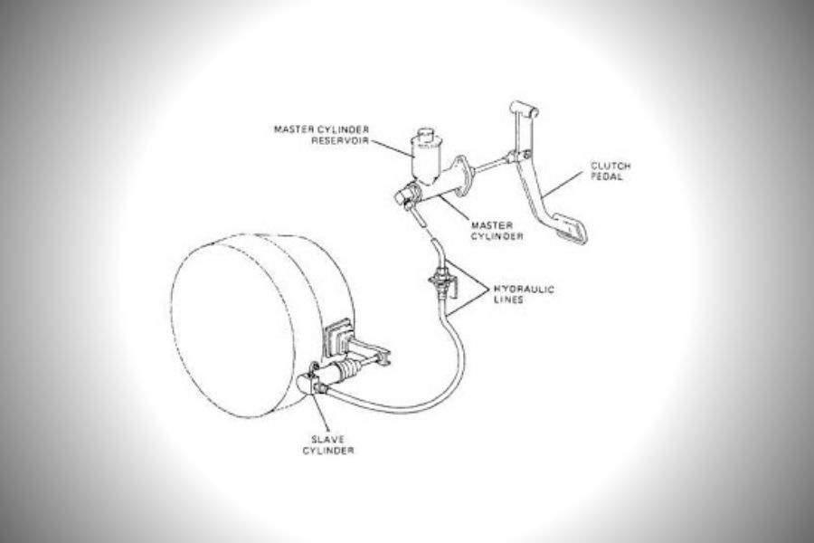
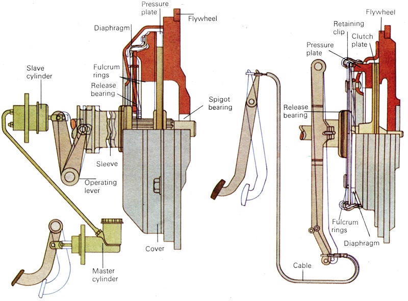
The figure given below shows the basic diagram of a Hydraulic clutch. The hydraulic clutch consists of various parts, such as the clutch pedal, master cylinder, hydraulic pipe, slave cylinder, release fork, release bearing, diaphragm spring, pressure plate, splined sleeves, clutch plate, and flywheel. Now we will study one by one in detail, #1.

Mastering the Basics of Hydraulic Clutch Systems
The below figure shows the diagram of a hydraulic clutch system used in an automobile. It consists of the following parts. 1) Flywheel: The flywheel is connected to the engine crankshaft.

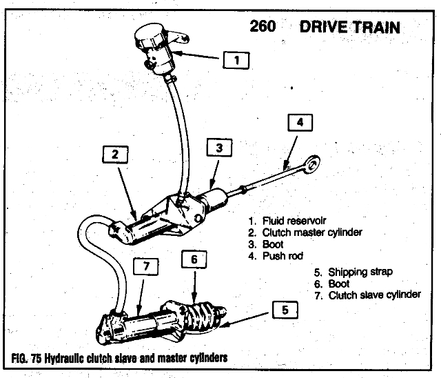
Repair Guides Clutch Master Cylinder And Reservoir
I. Hydraulic Actuation Wet or Dry Operation. Schematic # 1: Displays a typical circuit diagram for a hydraulically actuated wet or dry-running disc clutch. The pump (C) draws the oil through the filter (D) from the reservoir (H) and passes it under pressure to the operating pipeline. The operating pressure is adjusted by the limiting valve (E).

Clutch Hydraulics
Diaphragm clutch Clutch plate Surface of friction Pressure plate Master cylinder Slave cylinder & pushrod Flywheel Diaphragm springs Splined sleeves
How to Replace the Hydraulic Clutch Assembly
Using an aftermarket reproduction clutch pedal as the example, dimension #1 is 13.25 inches. There are two different stock pushrod holes available (measurement #2): three inches and 3.625 inches. To determine pedal ratio, divide figure #1 by #2. Here's how the ratios look for our example: 13.25 / 3 = 4.41 ratio. 13.25 / 3.625 = 3.63 ratio.

Hydraulic Clutch Linkage Keeping in touch with the clutch
A hydraulic clutch is a system in vehicles that uses hydraulic fluid to transfer force from the clutch pedal to the clutch assembly. This design offers smoother and more consistent clutch engagement, making it easier to shift gears and improving overall driving experience. Fig 1: Hydraulic Clutch